CAP.01
New board design
Schematic capture, managed libraries, placement, and layout for a design that starts as a blank sheet — built as a clean, maintainable Fusion 360 Electronics project.
PCB DESIGN / FUSION 360 ELECTRONICS / CLI SYSTEMS
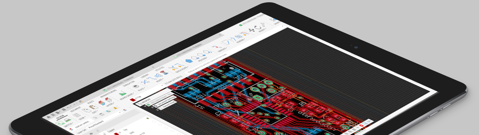
We design and finish printed circuit boards in Autodesk Fusion 360 Electronics — schematic, multilayer layout, and true ECAD/MCAD integration, so the board fits your enclosure the first time. Existing Fusion or EAGLE project, or a blank canvas, we take it all the way to a manufacturing package.
Who we are
FusionPCB is the PCB design practice of CLI Systems. We take on the boards that need to actually work in the field — not entry-level, not hacked together, not "close enough."
Bring us a brand-new design and we'll carry it from schematic capture through layout, 3D fit, verification, and a fabrication-ready package. Bring us an existing Fusion 360 or EAGLE project that stalled, needs a respin, or needs cleaning up, and we'll pick it up mid-stream and finish it right.
Because it's all in Autodesk Fusion 360 Electronics, the board and the enclosure live in one model — so you get design files, clean libraries, and a board that actually fits the product, not just the schematic.
What we do
A full-stack design service built around Fusion 360 Electronics — where the board and the mechanical design live together, so what you ship actually fits.
Schematic capture, managed libraries, placement, and layout for a design that starts as a blank sheet — built as a clean, maintainable Fusion 360 Electronics project.
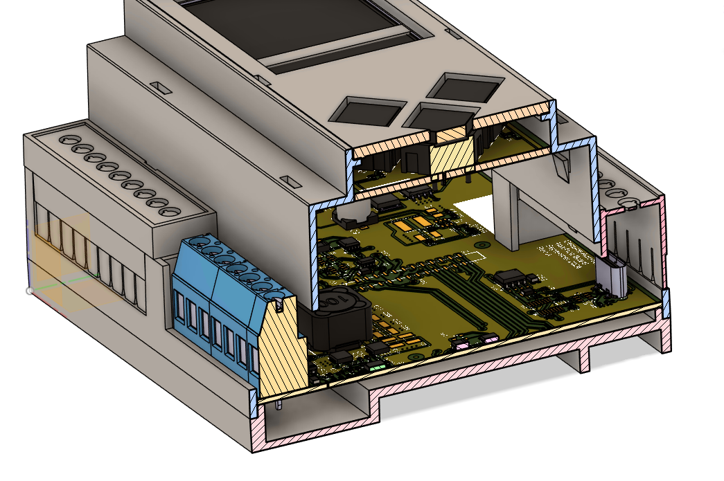
Your PCB and its enclosure in one model. We lay the board out in 3D against the mechanical design and push-pull changes both ways, so fit problems get caught long before a prototype.
Inherited a stalled Fusion 360 project or a legacy EAGLE design? We pick it up mid-stream, clean up the libraries and DRC debt, migrate it forward, and get it back to buildable.
Controlled stackups up to 16 layers, plane management, controlled impedance, and length matching — disciplined routing for the signals that actually care.
Managed libraries with symbols, footprints, 3D models, and supplier / BOM data — so parts place cleanly, the 3D board is accurate, and procurement isn't a guessing game.
Gerbers, drill files, IPC-2581 / ODB++, BOM, assembly drawings, pick-and-place, and a DFM review — a package your fab can build without guessing.
Selected work
 3D · RENDER
Fusion builds a true 3D model of the populated board from real component geometry — so design reviews happen on the actual product, not a flat plot. We catch collisions, connector access, and mechanical fit before anyone cuts a prototype.
The same model produces photoreal renders for datasheets, proposals, and stakeholder sign-off, straight out of Fusion 360.
 LAYOUT · 3D FIT
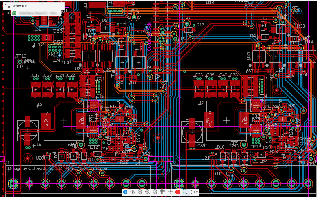
Tight placement and disciplined routing worked directly against the mechanical model — connectors, mounting holes, and keep-outs placed to the enclosure, with component heights and clearances checked in 3D before fab.
 ASSEMBLY · MULTI-BOARD
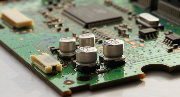
Several rigid boards designed to work as one product, joined by board-to-board connectors — each board laid out to its own mechanical envelope in Fusion, with the full stack assembled and checked in 3D so mating, spacing, and fit are right before fab.
How it works
We go through the schematic, constraints, layer stackup, and the mechanical model, and agree on DFM and fit targets before a single trace is drawn.
Placement, plane strategy, controlled impedance, and routing — laid out in 3D against the enclosure, with checkpoints so you see the board take shape.
Clean DRC, a DFM / DFA pass, and a 3D fit check against the mechanical model — with fabrication details confirmed against your chosen manufacturer.
You get the full manufacturing package plus the source Fusion 360 project — documented, and yours to keep.
Get in touch
New design, respin, or a project that needs rescuing — send the details and we'll come back quickly with next steps. We promise to respond fast.